|
|
|
|
|
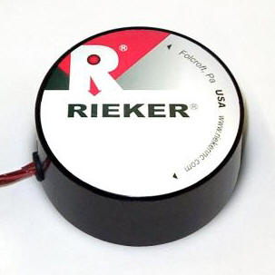
专业销售美国RIEKER传感器、RIEKER倾角传感器、RIEKER电子罗盘、RIEKER陀螺仪、RIEKER加速度计 RIEKER陀螺仪工作原理:高速旋转的物体的旋转轴,对于改变其方向的外力作用有趋向于铅直方向的倾向。而且,旋转物体在横向倾斜时,重力会向增加倾斜的方向作用,而轴则向垂直方向运动,就产生了摇头的运动(岁差运动)。当陀螺经纬仪的陀螺旋转轴以水平轴旋转时,由于地球的旋转而受到铅直方向旋转力,陀螺的旋转体向水平面内的子午线方向产生岁差运动。当轴平行于子午线而静止时可加以应用。型号:SBS1U……
销售美国RIEKER传感器、RIEKER倾角传感器、RIEKER电子罗盘、RIEKER陀螺仪、RIEKER加速度计
产品图片 产品名称/型号 产品简单介绍
2056倾斜仪、角度水平仪、2056E倾角传感器,系列Rieker倾角水平仪,升降天车、起重机手臂、水平测量、
2056水平仪/2056E倾角水平仪/倾斜仪 Manual Inclinometer: Model 2056E Commonly referred to as
a Clinometer (as in typical marine applications like boating) Two (2) scales,
two (2) ranges Top Scale gives accurate 1º readings - usef
起重、吊车、挖掘机、机械手臂角度指示仪、倾角传感器
4120L 臂角指示器:型号4120、4120WWL、4120WWL- 12V 吊车手臂指示仪、背光为较高的亮度,在光线不足的或夜间操作(无背光可选)
符合美国国家防火协会(NFPA)1901年用于汽车消防设备标准: 20.4云梯操作位置 工作温度:-50° F至+180° F 坚固的聚碳酸酯制造安装容易
4120一般规格手册 型号4120 WWL- 12V Specificaitons
RDS7 - BB 数字球倾斜仪
RDS7 - BB 数字球倾斜仪 倾角传感器 瑞可 根据从交通和运输部工程师Rieker推出了领先的RDS7 -
BB的球倾斜仪行业的最新版本全国反馈。在-09版本允许运营商之间切换观看的度数或百分比等级的角度。它还提供了输入功率的车辆(8 30V直流非经DSUB连接器调节)没有点烟器插头插座或永久硬接线线路的解决方案。
最主要的特色 - 现在的标准 - 是能够调整行程的± 10 °角度设置到适当的角度,指出在贵国的通过MUTCD(设置安全曲线
球形倾斜仪 1023W1
银球指示:手动及电子 1023W1
所谓“银球指标”是指一种可以被用于确定安全水平曲线(统一咨询)曲线速度倾斜的具体用途。它的措施倾覆力(侧面摩擦),在谈判一平曲线车辆度测量, -
无论它是一个孤立的曲线,多“S”曲线,或从高速公路匝道为/。通常由交通运输部和其他咨询机构。
姿态指示仪 专门为俯仰和滚动用于倾角在加油或装载平衡负载。
姿态指示仪 专门为俯仰和滚动用于倾角在加油或装载平衡负载。 这些专门为俯仰和滚动用于倾角在加油或装载平衡负载。
美国联邦航空局认证的样本指标和美国太平洋海运协会专利授权。 Rieker生产各种指标的态度为OEM飞机燃料系统的校准(也称为一个测斜仪)。以下是美国联邦航空局的型号认证的模式。我们的态度指标已作为原始设备上安装了许多飞机在生产阶段,或作为售后市场的升级,以取代老式的'铅锤的系统购买。
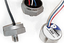
瑞可加速计 加速计:线性静态和动态
瑞可加速计 加速计:线性静态和动态 加速计:线性静态和动态
定义:加速度计是一种测量加速度,振动检测和测量,或测量重力加速度(倾角)的工具。加速度传感器可用于测量车辆,机械,建筑,过程控制系统和安全装置的振动。它们也可以用来衡量有或没有重力影响的地震活动,倾斜,机械振动,动态距离和速度。
精密机械背光倾角仪 背光倾角指示仪
背光倾角指示仪 说明 同样高的质量,从Rieker预期一个新的创新技术,即光管(非住宅),这样你可以清楚地看到球的位置。可与客户指定的住房或颜色最佳能见度管区。
这些引人注目的背光模型,专门用于消防车辆所需的所有仪器都点燃 - 1017和1023型号符合国家消防协会1901年标准的汽车消防设备
不过,这些都是非常适合任何行业,当仪器必须在低光或夜间操作可见。可用于单件和OEM量的一致好评。
H4系列坚固倾角传感器
H4倾角传感器 倾角传感器 H4的测斜仪可提供准确的倾斜在一个坚固的锌金属感应,保护环境的外壳。 该H4A提供模拟电压0 -
5V的输出,H4S提供了一个数字串行RS232输出。都有两种温度补偿金额可供选择,这取决于工作温度,提高在整个温度范围内精度。
外壳是专为在现场改造,无需重新安装孔钻(中心与滑块法兰常见的位置)。
产品图片 产品名称/型号 产品简单介绍
HLR750系列 防爆LVDT,ATEX防爆认证,UL/CE认证,GE公司汽轮机认证,UL/ULC Listed for Class 1, Division
HLR750-1000,HLR750-20000,HLR750-5000 HLR 750系列是3/4英寸直径、高可靠性LVDT是特别为汽轮机的使用环境而设计。这种额定使用温度为300°F
(150°C)的气密封交流供电LVDT可以满足 ATEX防爆A、B、C、D组,第2章,第1级 及IIC组,第2节,第1级长所述的危险环境认证。全不锈钢结构、过孔设计使LVDT的铁芯容易所两端得到更好的机械支持及铁芯导引,并且在污积秽环境容易清洁。获得
CD 375 微型LVDT位移传感器 高温105度 高压140mpa LVDT位移传感器
cd375 cd375-100 cd375-200 cd375-050 cd375-2000 位移传 马克罗传感器
推出的CD375系列是3/8英寸(9.5毫米)直径、交流供电的小型非接触式线性位移传感器,既能满足OEM客户的应用,也能满足终端用户的要求。CD 375
LVDT,CD375 微型LVDT位移传感器 耐高压140mpa LVDT位移传感器
PRH 812 通用线缆*流 位移传感器 LVDT
prh812 prh812-1000 prh812-1000-0135 macro sensors位
可选量程从±0.050英寸(±1.25毫米)至±10英寸(±250毫米),提供一个铁芯-内孔径向间隙为0.062英寸(1.6毫米)、铁芯直径为0.25英寸(6.35毫米)的标准铁芯。PR
812系列传感器具有分辨率高、重复性好、阻抗低、灵敏度高、线性好等LVDT技术特征。任何这种传感器的最大线性误差都不超过满量程输出的±0.25%最佳直线法
BBP 315超高精度微型 位移传感器 macrosensors BBPM315超小型位移传感器
BBP 315 马克罗传感器公司推出的 BBP系列8毫米直径铅笔式测量头为广泛的质量控制 、SPC及
工业度量应用提供超高精度的测量。它们用直线滚珠轴承与硬化、非旋转测量轴精密组合
,将径向游隙及边缘荷载的影响最小化。使测量头的重复性达到0.000006英寸(0.15微 米)。
GHSI 750 LVDT 位移传感器 回弹轴向密封型直流 4-20mA输出 GHSI750位移变送器
GHSI750 LVDT 磁致伸缩位移传感器 Macro Sensors GHESI750系列LVDT位移变送器
传感器公司推出的GHSI750系列直径为3/4’’回弹式回路供电LVDT位置变送器广泛适用于位置监测、反馈和尺寸计量。该系列传感器坚固、密封,完全采用不锈钢材料,满足一般工业用途。为抵御各种恶劣环境,线圈绕组采用密封封装,达到IEC
IP-68防护等级。输入/输出连接穿过密封轴向接头。0-10输出可选:GHSE750系列位移传感器
PR 812 通用线缆型交流 位移传感器
pr812-1000 pr812-1000-0135 pr812 可选量程从±0.050英寸(±1.25毫米)至 ±10英寸(±250
毫米),也提供一个铁芯-内孔径向间隙为0.031英寸(0.75毫米) 的标准铁芯。PR 812系列传感器具有分辨率高、重复性好、阻抗低、灵敏度高、线性好等LVDT技术特征。任何这种传感器的最大线性误差都不超过满量程输出的±0.25%最佳直线法。
Accelerometers:
Linear Static & Dynamic
|
 |
|
Definition
An
accelerometer is an instrument for measuring acceleration,
detecting and measuring vibrations, or
for measuring acceleration due to gravity (inclination).
Accelerometers can be used to measure vibration
on vehicles, machines, buildings, process control systems and
safety installations. They can
also be used to measure seismic activity, inclination, machine
vibration, dynamic distance and speed
with or without the influence of gravity.
Introduction
Rieker’s line of accelerometers (see comparison chart below) are
available in single, dual, or tri axial packages, with a variety
of frequencies and G ranges to suit many different test and
control applications. These accelerometer sensors are small
capacitive spring mass based with integrated electronics, which
do not require external amplifiers, providing for a very high
resistance to extreme acceleration overloads and
shocks. Available with Analog DC, digital Pulse-Width Modulated
(PWM) or frequency- modulated outputs.
|
 |
Features
-
Low Cost, Light Weight,
Compact
-
Hermetically Sealed
-
Operational
from -40°C
to +125°C
-
10,000 g impact & shock
resistant
-
Static DC
-
150 - 1500 Hz bandwidth
-
Dynamic
accelerometer with
low 1Hz corner frequency
-
Low noise
|
Accelerometer Sensors
(Single Axis)
|
Model |
Ranges |
Resolution |
Sensitivity |
Non-Linearity |
Output |
Supply
Voltage |
Dimensions
inches [mm] |
Bandwidth |
|
B1 |
±3g |
<0.001g |
100 mV/g |
<0.2% FS |
UbN = 5
Volt |
3 . . 6 VDC |
Ø
0.93" x 0.43"
[Ø 24 x 11] |
0 . . 160 Hz |
|
B2 |
±10g |
<0.005g |
23 mV/g |
0 . . 350 Hz |
|
B3 |
±50g |
<0.010g |
6.5 mV/g |
0 . . 550 Hz |
|
BDK3 |
±3g |
<0.001g |
150 mV/g |
<1% FS |
UbN = 5
Volt |
2 . . 16VDC |
Ø
0.87"
x 0.4"
[Ø 22 x 10] |
1 . . 300 Hz |
|
BDK10 |
±10g |
<0.005g |
60 mV/g |
1 . . 800 Hz |
|
BDK100 |
±100g |
<0.050g |
10 mV/g |
1 . . 1500 Hz |
|
Tri-axial Accelerometer / Inclinometer Package |
|
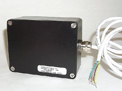
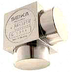
SBG3i |
Based on Sensor Model |
Based on Sensor Model |
Based on Sensor Model |
Based on Sensor Model |
4-20mA |
8 . . 30 VDC |
4.9" x 3" x 2.25"
[123 x 78 x
58] |
1 . . 1500 Hz |
Mounting Cubes
(Dual or Tri-Axial)
|
 |
BS24
Compatible with:
• NB3 Inclinometer
• B1, B2, and B3 Accelerometer |
 |
SW3
Compatible with:
•
N or NB3 Inclinometer
• B or BDK Accelerometer |
|
Attitude Indicators: Aircraft Fuel System
Calibration
 |
Definition
Specialized Pitch & Roll
Inclinometers for balancing loads during fueling or loading of
Commercial Aircraft
Introduction
manufactures a variety of Attitude Indicators (also known as an
Inclinometer) for OEM Aircraft Fuel Systems Calibration. Several
models must carry FAA certification for use on specific
Commercial Aircraft.
Our Attitude Indicators have been
installed as original equipment on many aircraft at the
manufacturing stage, or purchased as an aftermarket upgrade to
replace older style 'plumb bob' systems.
|
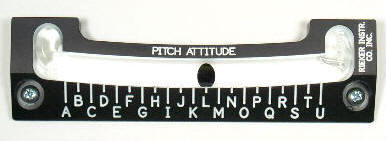
Part Number 5002P, FAA Certified Pitch Indicator |
Attitude Indicator Models
|
|
1017S5*
5002P*
5002R*
5005* |
A25-1
A25-3 |
A500
A502
A503
A505 |
|
* FAA Type Certified under our PMA
licensing agreement and ship with appropriate FAA documents. |
|
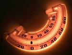
Backlit Inclinometers:
Mechanical "Ball-in-Tube" Type
|
 |
|
Description
These highly visible backlit models were specifically developed
for fire trucks that are required to have all instrumentation
lighted
models 1017 (±10º) and 1023 (±20º) comply with National Fire
Protection Association 1901 Standards for Automotive Fire
Apparatus.
However, these are well suited for any industry when
instrumentation must be visible in low light or night operation.
Available in single piece and OEM volumes alike.
Also
referred to as a clinometer or ball in tube level, the "-12VT"
models are
backlit versions of our precision inclinometers that have been
in the field for decades.
Same high quality expected from Rieker, with a new innovative
technique that lights the tube (not the housing) so you can
actually see the ball position. Available with customer
specified color zones on the tube for best visibility.
Equipment Types
Aerial lift trucks, Bucket/utility trucks, Cranes, Construction
Equipment, Conveyor and Material Handling Equipment, Emergency
and Fire trucks, Government and Military Vehicles, Trailers.
Contact us today for a quote. OEMs welcome, quantity pricing
available.
If you have an
application that requires custom specifications,
please contact us today
with your requirements. One of our engineers will be happy
to speak with you. |
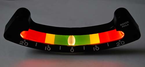
Photo
Above:
1023SPL3-8/12/20-12VT
Features
-
Long lasting Bright White LED Integrated into Existing
Housing.
-
Max current draw approx. 40mA at max input voltage.
-
Standard 12VDC or 24VDC input supply voltage (8-30VDC).
-
Same ALL-weather performance.
-
Same Precision Glass for Clear Viewing AND Best Ball Roll.
-
Same Rugged Die-Cast Aluminum Housing.
-
Same Customer Specified Color Warning Zones - easy to see
quick reference of safe or danger zones - on tube for best
visibility!
-
Same Operating Temperature
-40ºF to +160ºF
Applications
-
Quick and Accurate Visual Reference
for Low Light or Night Operation
-
Leveling, Balancing and helps Prevent Tip-over
-
Machining or Anywhere Precise Leveling Required
|
|
| |
Ball Bank Indicators: Mechanical and Digital
|
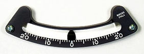
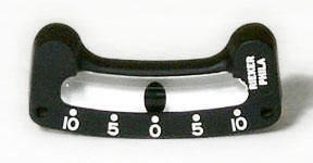
MechanicalBall Model 1023W1
Electronic
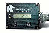
Digital Model RDS7-BB-09
|
|
Description
Rieker Ball
Bank Indicators reflect the operating procedures of Federal,
State, and local roads and highways, based upon the “Speed Zone
Theory” and “85th Percentile Speeds”, which is adapted by the
American Association of State Highway and Transportation
Officials (AASHTO); Institute of Transportation Engineers
(ITE) and as defined in the Federal and/or State Manual of
Uniform Traffic Control Devices, (MUTCD). Rieker
indicators have been the ball bank standard instruments used by
Federal and State Departments of Transportation Nationwide since
the 1950's. |
|
Definition
The term "Ball
Bank Indicator" refers to an inclinometer (or Accelerometer used
as an inclinometer) that is used for the specific purpose of
determining safe (uniform
advisory)
curve speeds
for
horizontal curves.
It
measures the overturning force (side friction), measured in
degrees, on a vehicle negotiating a horizontal curve.
If you have an application that
requires custom specifications,
please
contact us today with your requirements. One of our
engineers will be happy to speak with you. |
|
Mechanical Inclinometer:
1023W1 "The Original" Ball Bank
Indicator
-
±20º Inclinometer
-
The Original Inclinometer Used by DOTs
for Determining Safe Curve Speed Since the 1950's
-
1º Increments for Increased Accuracy,
smooth properly damped ball roll for precise real time readings
-
Quick Visual Reference, Early Warning
Indicator (ie Roll Over)
-
1000 Series Brochure
|
|
|
Model 1023W1 Specifications |
|
Dimensions |
5 3/8"w X 1 3/4"h X 5/8"d |
|
Degree
Range |
±20° |
|
Degree
Markings |
1° |
|
Case
Materials |
Black painted aluminum, engraved markings filled
white |
|
Tube
Construction |
Glass with black ball on white background |
|
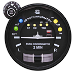
Digital Ball Bank Indicator
|
Overview
The RDS7-BB Digital Ball
Bank Indicator has been the DOT adopted standard electronic
measuring device for determining safe curve speed since the
1990's. The "-09" version allows the operator to adjust the
trip angle setting to the appropriate angle as indicated in
your State's adopted MUTCD (for setting safe curve speed
based on road type and MPH).
|
Features
-
Single Axis Measurement
- Adjustable LED (visual)
and Buzzer (audible) trip angle settings
- Buzzer on/off
- Cigarette Lighter Adaptor
- Angle measuring range ±30º
- LCD Display Resolution
0.1º
- RS232 output via serial
port connector (cable supplied)
- Easy installation
- Portable for multi-vehicle
use
- Simple display interface
|
Applications
- Safe Curve Speed Studies
- Ball-banking
- Vehicle Roll Monitoring
Industries
- DOT
- Public Works
- Accident Investigation
- Road and Transportation Construction
- Civil Engineering
|
|
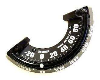
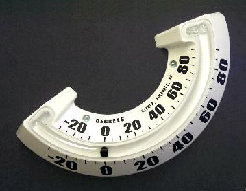
Boom Angle Indicators:
Digital Remote LCD & Mechanical
|
 |
|
All
cranes, derricks and certain lift equipment require some form of
boom angle indication. Boom angle indicators must be visually
readable by the operator. |
|
Mechanical
Boom Angle Indicator
Rieker 4120 Series of rugged ALL-Weather
Mechanical Boom Angle Indicators. |
Digital Boom Angle Indicator
Rieker RDSR3-BA-09 Digital LCD Display Remote
electronic boom angle indicator is sealed in a rugged case that
protects the sensor components from harsh environments. |
An inclinometer utilized for boom angle indication typically has
a degree range of -10 to +90 degrees to accommodate a variety of
boom types. The capacities that are listed on the crane load
charts are also based on and vary with the boom angle of the
crane.
For example: On hydraulic cranes, the boom angle is the angle
between the bottom of the boom butt and the horizontal while the
boom is under load (fig 1, view A). The boom angle on lattice
boom cranes is the angle between center line of the boom (from
the boom butt pins to the boom tip sheave) and the horizontal
while the boom is under load (fig 1, view B)
Figure 1
To check the accuracy of the boom angle indicator, place a
3-foot builders level on the center boom section and raise or
lower the boom until the level indicates the boom is level. At
this point the boom angle indicator should show the boom is at
zero degrees or adjusted to read zero degrees. |
|
Rieker Boom Angle Indicators
comply with current OSHA Standard 1926.550
|
OSHA -
Occupational Safety & Health Administration / U.S.
Department of Labor
-
Part
Title: Safety and Health Regulations for
Construction
-
Subpart Title: 1926 Subpart N: Cranes, Derricks,
Hoists, Elevators, and Conveyors
...1926.550(g)(3)(ii): Instruments and Components
......1926.550(g)(3)(ii)(A): Cranes and derricks with
variable angle booms shall be equipped with a boom angle
indicator, readily visible to the operator.
Click the
link below to visit the OSHA web site> |
|
|
Boom Angle Indicators:
Mechanical Type 4120 Series
 |
|
 |
 |
 |
 |
|
4120WWL |
4120BBL |
4120WBL |
4120WWL-12V* |
|
Description
Rieker's rugged ALL-Weather Mechanical Boom
Angle Indicators are not affected by outdoor elements. These
instruments are made tough and will not rust, freeze, or
otherwise "hang up" like old fashioned pendulum style boom angle
indicators.
Like all of our instruments, each boom angle
indicator is properly damped for smooth reliable
readings. Designed for easy mounting with two screws for quick
and efficient retro-fitting in the field.
4120 Specification Brochure
(PDF)
*Available in a highly
visible backlit model for
increased safety - complies with National Fire Protection
Association 1901 Standards for Automotive Fire Apparatus.
Please note:
A
boom angle indicator is a quick reference for the operator.
The capacities that are listed on the
crane load charts are also based on and vary with the boom angle
of the crane. However, do
NOT rely on the boom angle indicator for radius accuracy
especially when the lift exceeds 75 percent of the rated
capacity. Use the radius measurement to determine the capacity
of the crane from the load charts and to avoid any possibility
of error.
4120 PART Numbers for
ordering |
Features
-
Oversized inclinometer with High Visibility
Markings - large numbers for easy read
-
Hermetically sealed - assures dust free
smooth and accurate reading
-
Weatherproof - will not rust or hang up
-
100% Polycarbonate Construction - direct
impact, shock, and vibration resistant
-
Easily installed - retrofit in the field,
only 2 screws needed
-
UV Resistant - fade resistant
-
Operational from -50° F to +180° F - will
not freeze or hang up
-
Right hand (R) or left hand (L) models
available - read from either side of boom
|
|
Left
Side Boom Mount
4120WWL
4120WBL
4120BBL
4120WWL-12V |
 |
Right
Side Boom Mount
4120WWR
4120WBR
4120BBR
4120WWR-12V
|
|
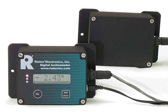
Boom Angle:
RDI Digital LCD Boom Angle Indicator
|
 |
All cranes,
derricks and certain lift equipment require some form of boom
angle indication. Boom angle indicators must be visually
readable by the operator. |
|
Rieker Boom Angle and Tilt / Level Indicators Comply with
Current OSHA Standard 1926.550 |
|
Model RDSR3-BA-09 General Specifications |
Features
- Nema 4 rugged Aluminum housing
- Industrial Temperature Compensation over -40/+85ºC
- Angle range -10 to +90º
- Backlit LCD Display Resolution of 0.1º
- Adjustable LED trip settings
- 8-30VDC non-regulated supply
- Military Style Amphenol Circular Connectors for
interface cable
- Remote box has mounting feet for easy field
installation and zero calibration
- Relative "Temporary" Zero
- Comply with Current OSHA Standard 1926.550
|
|
Description
Rieker's Digital Boom Angle
Indicator Remote Inclinometer Package (model RDSR3-BA-09) is an
extension of the RDI series of digital inclinometers.
Like the 4120, our electronic
boom angle indicator is sealed in a rugged case that protects
the sensor components from harsh environments. The RDSR3 is
supplied as a calibrated set featuring an environmentally sealed
measurement sensor package and a separate LCD display box
(connected by an interface available in various lengths). All of
the standard RDI features have been incorporated into this
remote sensing package, modified specifically to comply with
OSHA and other safety regulatory agencies specifications for
Boom Angle Indicators.
The display model comes standard
with green, yellow, and red LED lights (with adjustable trip
setting) provide the operator a bright fast visual warning of
safe and unsafe operating conditions. The green light indicates
safe operating zone, yellow as the early warning, and red as the
danger zone. An optional audible alarm model is also available -
the red LED on the front panel display is tied directly to the
buzzer.
The RDSR3-BA-09 comes standard
with Relative Zero and Min/Max Angle functions. The Relative
Zero allows the operator to temporarily zero the digital readout
to obtain relative slope changes. The Min/Max function provides
the smallest and largest angle since the last reset.
Please note: A
boom angle indicator is a quick reference for the
operator to know what angle the boom is at.
The
capacities that are listed on the crane load charts are also
based on and vary with the boom angle of the crane.
However, do NOT rely on the boom angle indicator for radius
accuracy especially when the lift exceeds 75 percent of the
rated capacity. Use the radius measurement to determine the
capacity of the crane from the load charts and to avoid any
possibility of error. |
|
Total Solutions:
Curve Advisory Reporting Service (CARStm)
|

Introduction
Rieker Inc., the leader in ball-bank instruments, introduces for
2015 the only complete service for establishing uniform safe
advisory safe curve signage at a State-wide level.
SAFETY FIRST
- Allows driving with traffic - any
speed. CONSISTENCY
- Meets FHWA 2009 MUTCD requirements.
ON-TIME Project Completion
- saves man hours & budget.
Now available through authorized fully trained and certified
service providers - complete turnkey to project based solutions.
If interested in becoming an Authorized
CARS Provider call today to speak with one of our CARS Solutions
experts.
Call us today to find the service provider in your state -
610-500-2000 - and learn how
Rieker CARS Solution will help you meet the FHWA mandate for
re-surveying all required roadway horizontal curves by 2019. |
Description
The Curve
Advisory Reporting Service (CARS™) automatically captures
all road data needed - in just one pass with traffic. Then
auto-uploads to the CARS online app for automated Horizontal
Curve Advisory Speed Reporting.
Rieker
CARS service reflects the operating procedures of Federal,
State, and local roads and highways, based upon the “Speed
Zone Theory” and “85th Percentile Speeds”, which is adapted
by the American Association of State Highway and
Transportation Officials (AASHTO); Institute of
Transportation Engineers (ITE) and as defined in the Federal
and/or State Manual of Uniform Traffic Control Devices, (MUTCD).
CARS Media:
|
CARS
Service Features
-
Safe & Continuous Operation
-
1
Pass each direction!
-
With Traffic!
-
FHWA
Compliant
-
Meets Federal MUTCD Requirements
-
Integrated GPS
-
Key Data Collection
-
Cloud Reporting
-
Automatic upload of survey data
-
Software allows review of detailed road
survey data
-
Generates reports for recommended curve speed
-
Allows for customization of horizontal limits
to meet individual State requirements
-
Secure
Online
Data Storage
-
Automated Curve Speed Calculations
|
|
Circular Bubble
Levels: Precision "Bulls-Eye"
|
 |
|
|
|
Description
Also referred to as a
“bulls-eye” level, the C000X Series of Circular Bubble Levels
provide accurate measurement of level in a rugged machined
Aluminum housing (Anodized black). Several sizes available to
fit any space requirement.
Manufactured to exacting specifications, the
accuracy is guaranteed and maintained through the use of
precision ground glass and machined Aluminum.
Rigorous testing
completed to assure high performance over long-term all weather
conditions, including industry
standard ASTM Salt
Fog survivability.
Each instrument is filled with
a special damping fluid that controls the movement of the
bubble, for smooth accurate readings. The fluid combined with
large, clear markings make it easy to get quick, accurate
readings under a wide variety of severe environmental
conditions.
These precision circular vials
have three mounting holes for installation convenience and
calibration. Since most mounting surfaces may vary, for exact
zero calibration the C000X-A models all come with mounting
hardware.
Contact
us today for a quote. OEM quantity pricing available.
If you
have an application that requires custom specifications,
please
contact us today
with your requirements. One of our engineers will be happy
to speak with you. |
Features
Applications
-
Quick Accurate Visual Level Reference
-
Leveling, Balancing and Preventing Tip-over
-
Machining or Anywhere Precise Leveling
Required
Equipment Types
-
Aerial
lift trucks
-
Bucket/utility trucks
-
Cranes
-
Construction Equipment
-
Conveyors
& Material Handling
-
Fire
Aerial Ladder Rigs
-
Government
and Military Vehicles
-
Recreational Vehicles (RV)
-
Trailers
|
|
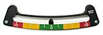
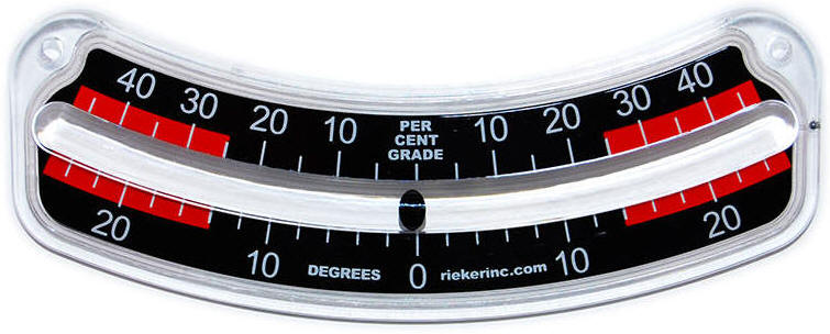
Gradiometers: Mechanical
& Electronic Digital LCD Display
|
 |
|
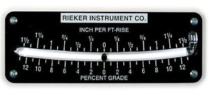
Model 5012P |
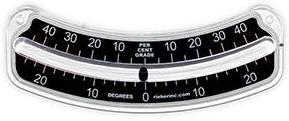
Model 2064EGM |
RDI
Digital Inclinometer Series
|
|
Mechanical "Ball-in-Tube" Type
Gradiometers |
Digital LCD Display Type |
Description
These precision instruments aid
the operator with quick visual indication of grade or slope.
Applications include bull dozers,
excavators, motor graders, pavers, plows, trenchers or other
equipment. The
digital version (RDI Series) can also be used to monitor
and control equipment.
If you have an application that requires
custom gradiometer specifications,
please contact us today
with your requirements. One of our engineers
will be happy to speak with you.
|
Definition
A Gradiometer - another type of inclinometer
- is used to accurately determine any slope or grade angle
quickly and easily. These precision instruments provide
accurate readings in either percent grade, degrees of
inclination, or inch per foot rise. |
|
Inclinometers:
Mechanical & Electronic
|
 |
 |
|
Mechanical |
Electronic |
|
Mechanical Inclinometers |
Inclinometer Sensors & Accelerometers |
Digital LCD Display Inclinometers |
|
|
 |
|
|
Precision
"ball-in-tube" Clinometers
Slip Indicators
Custom Tubes
Color
Warning Zones
Backlighting |
Single & Dual Axis
0-5VDC
0-10V
4-20mA
RS232
RS485
PWM |
Digital LCD Display
Remote Angle Monitoring
with
Analog(0-5V), Digital Serial (RS232), and Switch Outputs |
Inclinometer is an instrument for
measuring angles of slope and inclination of an object with
respect to its gravity by creating an artificial horizon. It is
also known as a tilt sensor, tilt indicator, slope meter, slope
gauge, gradient meter,
gradiometer, level
gauge & level meter. An inclinometer is commonly used in
different industries like
Aviation, civil
engineering, Government, Marine, Military, and Transportation
for platform
leveling, boom angle indication and slope angle measurement. The
tilt angle range is the range of desired linear output measured
in degrees. Important specifications to consider when searching
for tilt sensors and inclinometers are the tilt angle range and
number of axes.
|
If you have an application that
requires custom specifications,
please contact us today
One of our engineers will be happy
to speak with you.
Product Summary Catalog
Full Product Catalog |
|
Mechanical Inclinometers: Precision
"Ball-in-Tube" Type
 |
|
 |
 |
|
|
Inclinometer Model
1017SPL3-3.5/8/10 |
Gradiometer Model
2064EGMSPL-A |
Boom Angle Indicator Model
4120BBL |
|
Description
Rieker manufacturers
mechanical inclinometers using precision glass
or Polycarbonate tube and ball
construction with engraved or silk screened markings. Certain
models are available with customer specified color
warning zones. All our tubes are filled
with a special damping fluid that controls the movement of the
ball. The fluid combined with large, clear number and degree
markings make it easy to get quick, accurate readings under a
wide variety of severe environmental conditions.
Custom Color Zones
The color zone or "SPL" models are designed to instantly alert
the operator of tip-over danger utilizing highly visible color
zones: e.g. RED = tip-over danger; GREEN = safe operation. The
color zones are based on degree settings specified by the
customer - these must be specified at time of order. 1, 2 or 3
color zones available in Green, Yellow, and/or Red.
If you have an application requiring custom specifications,
please
contact us today - one of our application experts will be
happy to speak with you.
|
Features
Applications
-
Quick Visual of Angle
-
Platform Level
-
Roll Over
Early Warning
-
Slope
Indication
-
Percent
Grade
Equipment
-
Aerial Ladder Rigs
-
Aerial Lift Trucks
-
Aircraft
-
Barge
Cranes
-
Boom
Trucks
-
Construction Equipment
-
Cranes
-
Fire
and Rescue Trucks
-
Government Vehicles
-
Graders
and Excavators
-
Marine
Vessels
-
Military Equipment
-
Offshore
-
Sail
Boats
-
Submarines
-
Utility Trucks
|
Mechanical
Inclinometer Part Numbers:
|
Model |
Degree Range |
Degree
Increments |
Dimensions (w x
h x d) |
|
1005 |
±5° |
0.5° |
6"
X 1 5/8" X 5/8" |
|
1017 |
±10° |
2° |
6"
X 1 5/8" X 5/8" |
|
1017S5* |
±5° |
0.5° |
6"
X 1 5/8" X 5/8" |
|
1017W1 |
±10° |
1° |
6"
X 1 5/8" X 5/8" |
|
1017SPL2 |
±10° |
2° |
6"
X 1 5/8" X 5/8" |
|
1017SPL3 |
±10° |
2° |
6"
X 1 5/8" X 5/8" |
|
1023 |
±20° |
5° |
5
3/8" X 1 3/4" X 5/8" |
|
1023N |
±20° |
1° |
5
3/8" X 1 3/4" X 5/8" |
|
1023W1 |
±20° |
1° |
5
3/8" X 1 3/4" X 5/8" |
|
1023SPL2 |
±20° |
5° |
5
3/8" X 1 3/4" X 5/8" |
|
1030 |
±10° |
1° |
4
1/2" X 1 1/2" X 7/8" |
|
1030SPL |
±10° |
1° |
4
1/2" X 1 1/2" X 7/8" |
|
1040* |
±10° |
5° |
2
9/16" X 1 1/8" X 1/2" |
|
2055 |
±60° |
5° |
6"
X 2 1/2" X 3/8" |
|
2055E |
±60° |
5° |
6"
X 2 1/2" X 3/8" |
|
2056 |
upper scale ±6°
/ lower scale ±60° |
upper scale 1° /
lower scale 5° |
6"
X 3 3/4" X 3/8" |
|
2056E |
upper scale ±6°
/ lower scale ±60° |
upper scale 1° /
lower scale 5° |
6"
X 3 3/4" X 3/8" |
|
2058 |
±45° |
±10° in 2½°
Increments
±10° to
45° in 5° Increments |
6
1/2" X 2 3/8" X 3/8" |
|
2058E |
±45° |
±10° in 2½°
Increments
±10° to
45° in 5° Increments |
6
1/2" X 2 3/8" X 3/8" |
|
2064EM |
±26° |
2° |
6"
X 2 3/8" X 3/8" |
|
2064EGM |
±26° |
2°,
(5%) |
6"
X 2 3/8" X 3/8" |
|
2064EGMSPL |
±26° |
2°,
(5%) |
6"
X 2 3/8" X 3/8" |
|
490 |
-10° through
+80° |
5°
(right or left orientation) |
6"
X 2 11/16" X 3/8" |
|
4120 Series** |
-30° through
+90° |
5°
(right or left orientation) |
14"
X 6 3/8" X 1 3/4" |
|
5012P |
±13% Grade ±1.5
Ft/Rise |
1%
(1/8 FT/Rise) |
8"
X 2 7/8" X 3/8" |
*FAA Type
Certified under our PMA licensing agreement and ship with appropriate
FAA documents.
**Backlit
for better visibility, specifically for low light or night use. |
Electronic Inclinometers:
Tilt & Acceleration Sensors
|
 |
|
Description
Rieker provides a complete line of inclinometer
and accelerometer sensors. These sensors
are used for vehicle tilt monitoring, slope measurement, boom
angle indication, hydraulic motion control, wheel alignment,
vibration indication, and pitch & roll measurement. Semi-custom
and custom products available, contact us today to discuss your
needs.
The electronic inclinometer sensors are gravity
based with no moving parts and nothing to break - very reliable
for rugged applications.
Rieker also manufactures a versatile series of
digital inclinometers with LCD display, multiple outputs
(including analog, digital and switch) making it the most
customizable angle monitoring and early warning tilt indication
system on the market today. |
INDEX
Related Documents
|
Inclinometer Sensors
|
Series |
AXIS |
Range |
output |
input
supply |
IP rating |
dimensions |
|
H4 |
SINGLE |
up to 360º |
0...5V, RS232,
4...20mA,
RS485 |
8...30VDC |
67 |
Ø 1.95" x 1.1"
[Ø
49.6 x 28] |
|
H5 |
SINGLE |
up to ±90º |
0...5V, 0...10V,
RS232 |
12...30VDC |
67 |
Ø 2.52" x 1.1"
[Ø
64 x 28] |
|
H6-Flex |
DUAL |
scalable |
4...20mA,
RS485, CAN |
11...30VDC |
68 |
3.26" x 4.34" x 1.8"
[83 x 110.3 x 45.7] |
|
N |
SINGLE |
up to
±70° |
Analog mV |
3...6VDC |
65 |
Ø 1.46" x 0.45"
[Ø
37 x 12] |
|
NG360 |
SINGLE |
360° |
RS485 |
8...15VDC |
65 |
Ø 2.64" x 0.83"
[Ø
67 x 21] |
|
NGU |
SINGLE |
up to
±80° |
0...5VDC |
8...30VDC |
65 |
Ø 2.64" x 0.83"
[Ø
67 x 21] |
|
NGi |
SINGLE |
up to
±80° |
4...20mA |
8...30VDC |
65 |
Ø 2.64" x 0.83"
[Ø
67 x 21] |
|
NB3
|
SINGLE |
±10º |
Analog mV |
3...6VDC |
65 |
Ø 0.93" x 0.43"
[Ø 24 x 11] |
Back To Top
Accelerometer Sensors
|
SERIES |
AXIS |
Range |
Bandwidth |
output |
input supply |
dimensions |
|
B |
Single |
up to
±50g |
up to
550 Hz |
Analog mV |
3...6VDC |
Ø
0.93" x 0.43"
[Ø 24
x 11] |
|
BDK |
Single |
up to
±100g |
up to
1500 Hz |
Analog mV |
2...16VDC |
Ø
0.87" x 0.4"
[Ø 22
x 10,16] |
Back To Top
Sensor Packages
|
SERIES |
AXIS |
Range |
OUTPUT |
input supply |
IP rating |
Dimensions |
|
SB1i |
Single |
up to
±80°
or ±100g |
4...20mA |
8...30VDC |
65-67 |
3.86" x 2.52" x 1.42"
[98 x 64
x 36] |
|
SB1U |
Single |
up to
±80°
or ±100g |
0...5V |
8...30VDC |
65-67 |
3.86" x 2.52" x 1.42"
[98 x 64
x 36] |
|
SB2i |
Dual |
up to
±80°
or ±100g |
4...20mA |
8...30VDC |
65-67 |
3.86" x 2.52" x 1.42"
[98 x 64
x 36] |
|
SBG2U |
Dual |
up to
±80°
or ±100g |
0...5V
|
8...30VDC |
65-67 |
4.84" x 3.07" x 2.24"
[123 x
78 x 58] |
|
SBG3i |
Tri |
up to
±80°
or ±100g |
4...20mA |
8...30VDC |
65 |
4.84" x 3.07" x 2.24"
[123 x
78 x 58] |
|
SBL1i |
Single |
up to
±80° |
4...20mA |
8...30VDC |
65 |
7" x 7" x 3.94"
[178 x
178 x 100] |
|
SBL1S |
Single |
up to
±80° |
4...20mA,
0...5VDC,
relay |
8...30VDC |
65 |
7" x 7" x 3.94"
[178 x
178 x 100] |
|
SBS1U
SERVO |
Single |
±1° |
±5V |
12 or 24 VDC
|
65 |
3.86" x 2.52" x 1.42"
[98 x 64
x 36] |
Back To Top
ATEX or CSA (Hazardous Location) Sensor Packages
|
SERIES |
AXIS |
Range |
OUTPUT |
input supply |
Certification |
Dimensions |
|
SB2i |
Single or Dual |
up to
±80°
or ±100g |
4...20mA |
8...30VDC |
ATEX
or CSA |
3.86"
x 2.52" x 1.42"
[98 x 64 x
36] |
Back To Top
SUB SEA Sensor Packages
|
SERIES |
AXIS |
Range |
OUTPUT |
input supply |
IP rating |
Dimensions |
|
H6-Flex |
Single or Dual |
scalable |
4...20mA, RS485,
CAN |
11...30VDC |
68 |
3.26" x 4.34" x 1.8"
[83 x 110.3 x 45.7] |
|
XB |
Single or Dual |
up to
±80°
or ±100g |
4...20mA,
0...5VDC
|
8...30VDC |
68 |
6" x 4" x 2"
[153 x 102 x 51] |
Back To Top
LCD Display Packages
|
SERIES |
AXIS |
Range |
OUTPUT |
input supply |
IP rating |
Dimensions |
|
RDI |
Single or Dual |
up to
±70° |
LCD,
0...5VDC, RS232,
Switch |
8...30VDC |
65-66 |
4.53" x 3.54" x 2.21"
[115 x 90 x 56] |
Back To Top
Tilt Switches
|
SERIES |
AXIS |
Range |
trip setting |
OUTPUT |
input supply |
Dimensions |
|
RDI |
Single or Dual |
up to
±70° |
adjustable |
Open
Collector or Relay |
8...30VDC |
4.53" x 3.54" x 2.21"
[115 x 90 x 56] |
|
SlopeAlert™ |
Single or Dual |
up to
±45° |
factory
set |
Open
Collector or Relay |
8...30VDC |
2.87" x 2" x 1.5"
[72.9 x 50.8 x 38.1] |
|
SB1S |
Single |
up to
±80° |
adjustable |
Open
Collector |
8...30VDC |
3.86" x 2.52" x 1.42"
[98 x 64
x 36] |
|
SBL1S |
Single |
up to
±80° |
adjustable |
relay |
8...30VDC |
7" x 7" x 3.94"
[178 x
178 x 100] |
|
Digital Inclinometers: RDI LCD Display
Systems
|
Rieker’s RDI SERIES
of digital inclinometers is a complete angle monitoring and
early warning system. Available in both single or dual axis
packages, these units provide accurate tilt sensing in an
rugged, environmentally protected housing - temperature
compensation can be added to increase accuracy over
temperature. The RDI is the most flexible and multi-purpose
digital LCD display inclinometer system on the market today. |
Features and Options
(not all are available in certain
combinations)
-
Single and
Dual Axis
-
Remote Angle
Sensing Packages
-
Input Ranges
from ±4° to ±70°
-
Output
Options:
> Analog 0-5V
> Serial RS232
> Open
Collector Switch Outputs
> Relay Switch
(12VDC or 24VDC)
-
Power Supply
Options:
> 8-30VDC
non-regulated
> 9V Battery
> 110VAC or
240VAC Wall Adaptor
> Cigarette
Lighter Adaptor
-
LCD Displays
Angle in either:
> Degrees
> Percent
Grade
-
0.1° or 0.01°
Display Resolution
-
Relative Zero
Button
-
Minimum /
Maximum Angle Button
-
Up to 4 Open
Collector Switch Outputs
-
Adjustable
Trip Angle Settings
-
High
Current-Sink Capability
-
Lamp/Solenoid/Relay Drive
|
Applications
-
Equipment Roll
Over/Slope Warning
-
Platform
Leveling
-
Speaker &
Sound System Coordination
-
Pitch and Roll
Monitoring
-
Vehicle Tilt
Monitoring
-
Antenna
Positioning
-
Safe Corner
Speed Determination
-
Boom Angle
Indication
|
Industries
-
Aerial Work
Platforms
-
Cranes &
Derricks
-
Refuse & Dump
Trucks
-
Agricultural
Equipment
-
Excavators,
Graders, & Pavers
-
Drilling &
Mining Equipment
-
Fire & Rescue
-
Rough Terrain
Fork Lifts
-
Timber
Processors
|
|
Assignment of Axis |
|
Slip Indicators:
Aircraft Turn & Bank
 |
Description
Rieker Inc has been
manufacturing slip indicators for the aircraft industry since
the early 1920's.
 Over
the years, Rieker has produced a custom and stock slip
indicators used for general aviation, commercial, industrial,
and military applications. Today, our slip indicators provide
the most reliable and consistent roll in the industry. Over
the years, Rieker has produced a custom and stock slip
indicators used for general aviation, commercial, industrial,
and military applications. Today, our slip indicators provide
the most reliable and consistent roll in the industry.
Click here for additional
information: (external web links)
If you have an application
that requires custom gradiometer specifications,
please
contact us today with your requirements. One of our
engineers will be happy to speak with you. |
Model
1040: FAA Certified |
|
|
Definition:
A "slip" or "skid" or "bank"
indicator provides an economic method of determining the lateral
differential movement when banking or turning in an aircraft.
The bank or slip indicator consists of a curved glass tube
filled with a damping liquid in which a small ball rolls.
When the craft is horizontal, the
ball is located in the lowest part of the tube; as the craft
banks, gravity holds the ball at the lowest point as the tube
rotates from side to side. The tube can be calibrated to show
the angle of banking.
|
|
Tilt Switches: Open Collector & Relay
 |
|
SlopeAlert Tilt Warning System |
RDI Series of Digital Inclinometers |
SB1S Inclinometer Package |
|
LOW COST Rough Terrain Tilt Switch |
LCD Display up to (4)
Open-Collector
Outputs |
0 to 5VDC Output + 2
Open-Collector Outputs |
Description
Rieker tilt indicating
instruments are utilized to provide a visual or audible alert to
warn operators of steep slopes and can be configured to disable
(or shut-off) equipment in the event of rollover - especially
useful for off-road construction equipment. These can be used in
any industry where a tilt warning is needed or required to
provide a safer condition.
Rieker tilt switches
vary from an economical approach if you are only looking for a
simple tip over warning (or "on/off" switch) as with the
SlopeAlert, to a constant feedback / visual readout of slope
angle with the versatile, semi-custom RDI Series of Digital
Inclinometers. Manufactured tough for off-road abuse and extreme
weather, all models offer easy to identify alert
characteristics. Click on the photos above for detailed
product information.
If you have an application
that requires custom gradiometer specifications,
please contact us today with
your requirements. One of our engineers will be happy to speak
with you. |
Definition
A tilt switch (also known as a
slope indicator
or inclinometer) generate an artificial horizon and measure
angular tilt (or slope) with respect to this horizon. The tilt
angle range is the range of desired linear output measured in
degrees. Common electrical outputs for inclinometers and tilt
sensors include, analog frequency or pulse width modulated,
analog voltage, digital (RS232) serial, and switched or alarm.
Other parameters to consider include operating temperature,
environment, shock, and vibration.
|
|
|
Electronic Sensors PDF Index
Experienced with the following or
Electrical/Mechanical Safety, EMI Immunity, MFG Process: CE,
CSA, MIL Spec, ISO
|
|
 |
|

 霍尔(电路)元件
 霍尔(电路)元件
 霍尔(电路)元件
 霍尔(电路)元件
 霍尔(电路)元件
 霍尔(电路)元件
 霍尔(电路)元件
 霍尔(电路)元件
 霍尔(电路)元件
 霍尔(电路)元件
 干簧管
干簧管