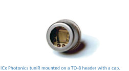
ICx Photonics offers a unique class of electrically pulsed,
high intensity infrared radiators for gas analysis,
spectroscopy, calibration and tactical identify friend or
foe (IFF) applications. These radiators feature a low
thermal-mass filament tailored for high emissivity. The
filament is fabricated using a patented process such that it
supplies bright IR power output while operating much cooler
than alternatives. This lower temperature operation reduces
the chance of igniting combustible gasses, improves power
efficiency, reduces heating of the optics and detectors, and
prevents illumination in the SWIR bands. These IR sources
are typically pulsed at rates from ½ to 10 Hz with several
hundred degrees of temperature modulation.
For demonstration and system design, ICx Photonics provides
an Evaluation Kit that includes a power supply for your
region. The Evaluation Kit drive card produces a flat-topped
current pulse of adjustable amplitude, length, and frequency
that can be run with the pre-programmed settings, or can be
connected to a PC for user control via included Windows TM
software.
The table below provides the specifications for each of our
broadband IR light sources. If you do not see a product that
meets your requirements, please contact us as we may be able
to provide a custom solution that meets your needs. Also, we
have a line of narrowband IR light sources which use MEMS
technology. Because of their spectral tuning, these are
extremely efficient devices suitable for battery powered
applications.
SPECIFICATIONS, PART NUMBERS, and WINDOW
OPTIONS:
| |
Parabola |
TO-8 |
Mulit-Element |
TO-5 |
TO-46 |
| |
 |
 |
 |
 |
 |
|
2 Element
|
4 Element
|
|
Windowless |
reflectIR-P1N |
NL8LNC |
NL82LNC |
NL84LNC |
NM5LNC |
NL46LNX |
Sapphire
2 to 5.25µm |
relfectIR-P1S |
NM8ASC |
NM82ASC |
NM84ASC |
NM5NSC |
N/A |
Germanium
7 to 12µm |
N/A |
N/A |
N/A |
N/A |
NL5NGC |
N/A |
Calcium
Flouride
2 to 9.5µm |
reflectIR-P1C |
NL8ACC |
NL82ACC |
NL84ACC |
NL5NCC |
N/A |
Rated
Temperature |
750°C |
Minimum
Resistance |
1.4 Ohms |
2.8 Ω |
1.3 Ω per Element |
2.5 Ω |
0.4 Ω |
Maximum
Resistance |
2.0Ohms |
4.5 Ω |
1.7 Ω per Element |
3.7 Ω |
1.0 Ω |
Maximum
Input
Power |
1.7 W |
2.2 W |
1.6 W per Element |
2 W |
1.1 W |
Modulation
Speed |
Constant - 30hz; 100% modulation <5hz |
Output
Radiation
Pattern* |
 |
 |
PULSED OPERATION
Although capable of running at duty cycles of up to 100 %
(DC) most users run the filaments with duty cycles of less
than 50%. Square-waveform constant current or constant
voltage drive schemes are the simplest and most cost
effective means of powering the sources. For constant
current drives, the power delivered to the source goes as I2
x R. As the source heats up, its resistance increases
slightly, causing the power delivered to the source to
increase during the “ON” portion of a pulse. For constant
voltage drives, delivered power goes as V2/R; therefore the
power delivered to the source tends to decrease slightly
during the length of a pulse. Other drive schemes can also
be employed; constant power or DC for example.
Owing to the extremely low thermal mass of pulsIR emitters,
shot-to-shot stability is directly related to drive circuit
stability. Variations in drive pulses will translate into
variations in output. To determine this we used a liquid
nitrogen cooled InSb detector available in our laboratory
for detecting energy in the 2-5 μm range. The pulsIR source
was driven with a constant-voltage drive circuit that
ensures pulse-to-pulse repeatability (standard deviation) of
5.3x10⁻⁴. Measurements of the InSb detector reading from 16
seconds of 10 Hz operation was measured to have a comparable
standard deviation of 6.8x10⁻⁴.
SOURCE LIFETIME
The following graph shows the results (to date) from an
ongoing extended life test experiment using an ICx Photonics
NM8ASC source. The source is being driven by a constant
current drive board at 1 Hz, 30% duty cycle at an
approximate temperature of 650°C. Two pyroelectric etectors
are monitoring the source output at two distinct
wavelengths. In the following chart, the circles show the
source output at 4.29 microns (CO2) while the diamonds show
the output at 3.9 microns (reference). The detectors are
mounted about four inches from the front face of the source
and a dry nitrogen purge is used to prevent water vapor and
carbon dioxide in the lab air from affecting the
measurement. The temperature in the lab is not very well
controlled however, and much of the variation (specifically
the bump at ~2000 hours) is due to room temperature swings.
The definition of failure, and thus the definition of
lifetime, is very subjective as each system has unique
sensitivity to drift (largely related to the A/D bandwidth).
We have encountered several applications which define
failure as >15% drift from the original power level, so we
will adopt this definition for the purposes of this
computation. The graph below shows that the median signal
level from the 3.9 and 4.29 μm detectors is roughly 4 volts;
the linear regression fits to the raw data indicate that
both of these signals are decreasing at a rate of 1x10⁻⁵
volts/hour. With our assumed signal drift tolerance of 15%
and 4 volt signal level, we require a 0.6 volt signal change
to signal failure of the light source [0.15 x 4]. With our
measured rate of change being 1x10⁻⁵ volts/hour it will take
approximately 7 years of continuous operation to obtain a
15% signal change [(0.6v)/(1x10-5v/hr)/(8760hrs/yr)]. Since
many systems utilize the ratio of the gas measurement to a
reference, they are sensitive not to signal changes, but to
change in the ratio of the two signals. With a measured
slope of 1x10⁻⁶ volts/hour and a 0.75 volt signal the same
computation yields a lifetime of 13 years. Since all of the
known filament degradation mechanisms are temperature
dependent, the time to 15% failure is strongly dependent
upon operating temperature or electrical power applied.
Therefore, caution should be used in extrapolating these
results to your application.

 红外光电系列